DSMS Civil engineering, steel design structure.
The fundamental process of structural design commences with the preparation of a structural concept, which is itself based on an architectural design for the structure. For simple, common forms of structure, it will be possible to prepare a concept design directly from the architectural design - typical solutions are well understood.
For more complex structures, or innovative designs, best practice is to develop the structural concept in conjunction with the architectural scheme, so that an efficient, appropriate solution can be developed.
Once the concept design has been established, the structural design can be completed, involving determination of loads, frame analysis and member verification.
Steel design:
Steel is ideally suited for design. Material properties are known and member properties are accurate, meaning that analysis is precise. Design rules are clear and mature, without undue conservatism, having been developed over many decades. There is a wealth of support resources, including software, to facilitate efficient design.
[top]Concept design:
The choice and design of the primary structure is a fundament part of the concept design of buildings, and ideally should be integrated with the development of the architectural design. Meeting client, planning and Building Regulation requirements are paramount, but there will be a range of structural forms that meet these requirements, each with its own advantages. The merits of different structural forms should be reviewed against the requirements for the structure. Key considerations include:

- Cost and speed of construction
- Building height and plot ratio
- Future flexibility and adaptability
- Site constraints including ground conditions
- The need for special structural arrangements in public spaces or circulation areas
- Floor grids and dimensional coordination with the planning grid
- Structural construction depth (ceiling to floor level)
- Servicing strategy and its coordination and integration with the structure (horizontally and vertically)
- Floor loadings
- Fire resistance
- Sustainability requirements.
The principal structural elements of a typical multi-storey building comprise floors, beams and columns. A wide variety of alternative forms and arrangements can be used in multi-storey steel framed structures to deliver the benefits of:
- Economy
- Shallow floor construction
- Integration of services
- Flexible, column-free floor space
- Reduced foundations
- Rapid on-site construction.
[top]Factors affecting choice of structural system
Floor grids define the spacing of the columns in orthogonal directions, which are influenced by:
- The planning grid (typically based on multiples of 0.6 m, 1.2 m or 1.5 m)
- The column spacing on the facade, to suit the external envelope (typically 5.4 m to 7.5 m)
- The intended use of the internal space
- The requirements for building services distribution.
The British Council for Offices (BCO) Guide to Specification[1] provides extensive guidance on the preparation of scheme designs.
For naturally ventilated offices, a building width of 12 m to 15 m is typically used, which can be achieved by two spans of 6 m to 7.5 m, with a column placed adjacent to a central corridor. Natural lighting also plays a role in choice of the width of floor plate. In larger buildings, a long-span solution provides a considerable enhancement in flexibility of layout. For air conditioned offices, a clear span of 15 m to 18 m is often used.
Floor-to-floor height will be an important consideration at the concept design stage. The table below gives typical floor to floor heights for buildings of different use.
| Prestige office | 4 - 4.2 m |
| Speculative office | 3.6 - 4.0 m |
| Renovation project | 3.5 - 3.9 m |
If planning restrictions limit overall building height, shallow floor solutions may be adopted, or solutions that involve integrating the services within the structural depth. Typical structural depths for different types of construction are given in the table below.
| Composite beam construction | 800 mm - 1200 mm |
| Cellular beams (with service integration) | 800 mm - 1100 mm |
| Precast concrete floors (7.5 m span) | 1200 mm - 1200 mm |
| Precast concrete floors (14 m span) | 1450 mm - 1450 mm |
| Shallow floor system or integrated beams | 600 mm - 800 mm |
Stability systems

The structural system required for stability is primarily influenced by the building height. For buildings up to eight storeys height, the steel structure alone may be designed to provide stability, but for taller buildings, concrete or braced steel cores are more efficient structurally. The following structural systems may be considered for stability.
Braced frames
For buildings up to eight storeys high, braced steel frames are commonly used with bracing members generally located within a cavity in the facade, or around stairs or other serviced zones.
A steel braced frame has three key advantages:
- A braced solution is less expensive than a continuous frame
- Responsibility for temporary stability lies with one organisation
- As soon as the steel bracing is connected, the structure is stable.
[top]Continuous frames
For buildings up to four storeys high, continuous frames may be used in which the multiple beam to column connections provide bending resistance and stiffness to resist horizontal loads. This is generally only possible where the beams are relatively deep (400 mm to 500 mm) and where the column size is increased to resist the applied moments. The connections between members are likely to be more expensive than those in braced frames.
[top]Concrete or steel cores
Concrete cores are the most practical system for buildings of up to 40 storeys high, with the concrete core generally constructed in advance of the steel framework. In this form of construction, the beams often span directly between the columns on the perimeter of the building and the concrete core. Special structural design considerations are required for:
- The beam connections to the concrete core
- Fire safety and robustness of the long-span construction.


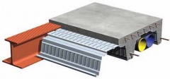
Braced steel cores may be used as an economic alternative where speed of construction is critical. Such cores are installed with the rest of the steelwork package. An example of a braced steel core is shown in the figure above middle.
Guidance for the design of cast-in steel plates for connecting structural steel beams to concrete core walls is available in SCI-P416. This publication provides a model for the design of simple connections that transfer shear force due to permanent and variable loads and a non-coincident axial tie force resulting from an accidental load case. It points out additional issues which must be considered where coincident shear forces and axial forces are to be dealt with. A sample design of a simple connection for a 610 serial size UB is presented, and the design of punching shear reinforcement for the wall is included. The guide discusses the responsibilities of the building structural engineer and the steelwork contractor and suggests where the responsibilities are best divided. It also considers the impact of deviations between the theoretical positions of the parts of the connection and their as-erected positions.
[top]Columns
Columns in multi-storey steel frames are generally H sections , predominantly carrying axial load. When the stability of the structure is provided by cores, or discreet vertical bracing, the beams are generally designed as simply supported. The generally accepted design model is that nominally pinned connections produce nominal moments in the column, calculated by assuming that the beam reaction is 100 mm from the face of the column.
For ease of construction, columns are usually erected in two, or sometimes three storey sections, i.e. approximately 8 m to 12 m in length. Column sections are joined with splices , typically 300 mm to 600 mm above the floor level.
[top]Floor systems
A wide range of floor solutions is available. Although steel solutions are appropriate for short spans (typically 6 m to 9 m), steel has an important advantage over other materials in that long-span solutions (between 12 m and 18 m) can be easily provided. This has the key advantage of column-free space, allowing future adaptability, and fewer foundations.
Floors spanning onto the steel beams will normally be either precast concrete units, or composite floors. The supporting beams may be below the floor, with the floor bearing on the top flange (often known as "downstand" beams), or the beams may share the same zone with the floor construction, to reduce the overall depth of the zone. The available construction zone is often the determining factor when choosing a floor solution.
| Form of construction | Typical solution |
|---|---|
| Low rise, modest spans, no restriction on construction depth | Downstand beams precast units or composite floors |
| Modest spans (less than 9 m), restricted construction depth | Integrated solutions – precast or composite floors |
| Low rise, long span (e.g. 15 m) | Downstand beams in the façade. Composite floors with secondary steel beams spanning 15 m |
| Medium and high rise, modest spans, no restriction on construction depth | Downstand beams, composite construction |
| Medium and high rise, long spans (to 18 m) restricted construction depth | Composite floors with cellular long span secondary steel beams |
The span range of various structural options in both steel and concrete are shown in the table. Long-span steel options generally provide for service integration for spans of over 12 m. Cellular beams and composite trusses are more efficient for long-span secondary beams, whereas fabricated beams are often used for long-span primary beams.

Long-span beams have gained in popularity in the commercial building sector because they offer the following benefits in design and construction:
- Internal columns are eliminated, leading to more flexible and efficient use of internal space
- Services can be integrated within the depth of the structure, and so the floor to floor depth is not increased
- Fewer components are required (typically 30% fewer beams) leading to reduced construction and installation time
- Fire protection costs can be reduced due to the massivity (weight : exposed profile) of the longer span members
- Steelwork costs are not increased significantly, despite the longer spans.
Foundations
In inner city and on difficult or brownfield sites, the time and cost of constructing the foundations has a major effect on the viability of a project. Although the weight of the frame is relatively small compared with the floors and walls, a steel frame can be significantly lighter than a comparable reinforced concrete frame. Further reductions in weight can be achieved by using light floor construction such as composite metal deck floors and lightweight concrete.
Difficult ground conditions may dictate the column grid. Long spans may be required to bridge obstructions in the ground. More generally, widely spaced columns reduce the number of foundations, simplifying the substructure construction and reducing cost.
[top]Integration of building services

Service runs can be integrated within the depth of the structure or separated by fixing them at a lower level.
Separation of zones usually requires confining the ducts, pipes and cables to a horizontal plane below the structure, which will increase the overall floor construction. However, the services remain readily accessible for maintenance and future refitting.
Integration of services and structure reduces the construction depth but requires a perforated structure; installation and subsequent refitting of services may be more difficult.
External envelope
Cladding systems that are used in multi-storey buildings depend on the building height and the degree of fenestration. Fully glazed facades are widely used, although provision for solar shading generally has to be made. Cladding systems include:
Brickwork
Ground supported up to 3 storeys. Supported by stainless steel angles attached to edge beams for taller buildings.
Glazing systems
Generally triple glazing or double layer facades supported on aluminium posts or glass fins.
Curtain walling
Aluminium or other lightweight facade that is attached to the perimeter steelwork.
Insulated render or tiles
Cladding system supported on light steel infill walls, mainly used in public sector buildings and residential buildings.
The external skin of a multi-storey building is usually supported off the structural frame. In most high quality commercial buildings, the cost of external cladding systems greatly exceeds the cost of the primary structure. This influences the design and construction of the structural system in the following ways:
- Reducing the floor zone may be cost-effective as it reduces the area of cladding.
- The perimeter structure must provide a satisfactory platform to support the cladding system and be sufficiently stiff to meet any deflection criteria.
[top]Structural principles
Once the structural concept has been fixed, the structural design may be completed. The structural design process involves the following steps:
- Calculating the permanent actions and determining the variable actions
- Identifying the load paths that carry the applied actions (vertical and horizontal) to the foundations
- Selecting preliminary sizes for members
- Analysis of the structure, if necessary, to determine design effects on individual members and deflections
- Analysis of the structure to assess sensitivity to second-order effects, allowing for these if necessary
- Verifying the members by ensuring the design resistance exceeds the design effects
- Verification of the members, and the frame, by ensuring the deflections do not exceed the limits given in the design Standard, or those specified by the Client.
Variable actions
Characteristic variable actions include:
- Imposed floor loads
- Imposed loads on roofs
- Wind actions
- Snow loads
- Actions on structures exposed to fire
- Actions during execution of buildings (for example during concreting of composite slabs and beams)
- Accidental actions (used when considering the requirement to avoid disproportionate collapse)
Characteristic variable actions should be determined from the appropriate parts of BS EN 1991-1[2] and the relevant UK National Annexes[3].
Analysis

For 'simple construction', frame analysis will not be necessary at the Ultimate Limit State (ULS), as the members can be designed in isolation. It may be necessary (or convenient) to use analysis software to determine the lateral deflections at the Serviceability Limit State (SLS) and when assessing frame stability. Analysis will be required for continuous frames.
Generally, elastic analysis is used. Plastic analysis (and elastic-plastic analysis) is generally only used for the design of portal frames .
Although manual methods of analysis may be used, most designers find it convenient to use readily available software .
Most software contains libraries of all the standard steel sections, with the associated member properties used in the analysis. Non-standard members may be modelled with equivalent section properties. Tapered or haunched members may be modelled with a number of short elements, each with different section properties. Curved members may be modelled with a series of straight members.
Common UK practice is to assume joints are either nominally pinned (and modelled as perfectly pinned) or nominally rigid (and modelled as perfectly rigid). It is then important to ensure that the physical details correspond to the design assumptions.
Sensitivity to second-order effects
All frames experience second-order effects, typically because under lateral loads (or simply due to frame imperfections), the vertical loads are no longer concentric with the bases. The effect of this displacement is not accounted for in a first-order analysis. Some frames are sufficiently stiff such that second-order effects are small enough to be ignored. When second-order effects must be accounted for, this can be achieved by using second-order analysis, or by a simple amplifier of the lateral loads.
All frames must be assessed for sensitivity to second-order effects, and these effects allowed for if necessary.
[top]Design Standards
The over-arching requirement for design in the UK is to satisfy the Building Regulations. Practically, design of steel structures will generally be in accordance with BS 5950[4] or the Eurocodes .
Building Regulations
Building Regulations require that a safe structure be constructed. Although a series of design Standards are cited in the Regulations, there is no absolute requirement that the listed Standards are used for design.
BS 5950
Although BS 5950[4] was withdrawn in March 2010, it is likely to be used for steel building design for a number of years. The advantages of design to BS 5950 include:
- Familiarity with the Standard enjoyed by experienced designers
- The extensive use of look-up tables within the Standard
- The specific sections of the Standard devoted to particular building types, such as portal frames.
Eurocodes
The Eurocodes are a set of unified structural design standards for use across Europe, developed by CEN (European Committee for Standardisation), to cover the design of all types of structures in steel, concrete, timber, masonry and aluminium.
In the UK, the Eurocodes are published by BSI under the designations BS EN 1990 to BS EN 1999; each of these ten Eurocodes is published in several Parts and each Part is accompanied by a UK National Annex (which must be used for construction in the UK) that adds certain UK-specific provisions.
In addition to the Eurocodes and the National Annex, non-contradictory complementary information (NCCI) is provided, to provide further guidance on the application of the Eurocodes.
National Annexes
The National Annex (NA) is an essential document when using any Eurocode Part; the relevant NA covers the country where the construction will take place. Where the opportunity is given in the text of the Eurocode, the National Annex will:
- Specify the value of factors, modify limiting values or formulae
- Specify which design method may be used
- Specify which options may be used, if they are given in the Eurocode
- State whether an informative annex may be used - such annexes are explicitly identified as being open to National acceptance.
- Identify NCCI.
NCCI
The National Annex may give references to publications and other guidance containing non contradictory complementary information (NCCI) that will assist the designer when designing a structure to the Eurocodes.
The Eurocodes omit some design guidance where it is considered to be readily available in text books or other established sources. Publications that contain such design guidance may be referenced in the National Annex as NCCI.
Several 'Published Documents' (PDs) are available, published by BSI . These NCCI documents are informative, without the status of a Standard, but are generally helpful reference documents for designers.
Basis of structural design
BS EN 1990[5] can be considered as the 'core' document of the structural Eurocode system as it establishes the principles and requirements for the reliability, serviceability and durability of structures. It also describes the basis for structural design and verification. The main sections of BS EN 1990[5] include:
- Requirements
- Principles of limit state design
- Basic variables
- Structural analysis and design assisted by testing
- Verification by the partial safety factor method.
Designers will refer to BS EN 1990[5] (and its National Annex[6]) for load factors and combination factors, used when determining design combinations of actions (ULS loads).
BS EN 1993-1 (Eurocode 3)
BS EN 1993-1 Eurocode 3: Design of steel structures comprises a set of general rules in twelve parts (BS EN 1993-1-1[7] to BS EN 1993-1-12[8]) for all types of steel buildings. The commonly used Parts include:
- BS EN 1993-1-1[7]. This Part provides most of the general rules used in the design of steel buildings, including material properties, guidance on analysis, the assessment of second-order effects and the calculation of member resistances.
- BS EN 1993-1-5[9]. This Part provides rules for members fabricated from plate, but also provides the rules for calculating the resistance of webs - typically verified under concentrated loads.
- BS EN 1993-1-8[10]. This Part provides the design rules for joints. It includes rules for the resistance of joint components, such as bolts and welds.
Additional rules are provided in separate Parts for other structures, e.g. BS EN 1993-2[11] provides design rules for bridges.
A comprehensive range of design guidance is available for use in the UK, all incorporating the influence of the UK National Annexes.
[top]Common structural systems :
Building frames may be broadly classified by their stability system, as braced or continuous frames . A portal frame is a particular type of a continuous frame. For multi-storey frames, a braced frame is likely to be most economical, because the fabrication effort for the joints in braced frames is generally much less than for joints in continuous frames. Continuous frames must be used when bracing cannot be provided within the structure.
Within both types of frame, a wide range of floor systems is available. Several floor systems utilise the benefits of composite construction , which will be the de facto solution for many structures. The floor systems in common use are briefly described in the following sections
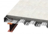
Composite construction

Composite construction is the dominant form of construction for the multi-storey building sector. Its success is due to the strength and stiffness that can be achieved, with minimum use of materials, utilising the compressive strength of concrete and the tensile strength of steel. Composite floors offer significant advantages related to speed of construction and reduced overall construction depth.
Composite floor slabs generally use either relatively shallow profiled steel decking , typically spanning up to 3.75 m, or deep deck systems, spanning up to 9 m (if propped during construction). Composite floor slabs may also be constructed using pre-cast planks as the permanent formwork.
Floor slabs may be formed from pre-cast planks, but still allow the supporting beam to be designed as a composite member.
Composite beams involve the transfer of force between the steel section and the concrete which it supports, preventing slip and thus ensuring the two elements perform as a composite whole. For beams located wholly under the slab (known as "downstand" beams) the transfer of force is commonly achieved using headed shear studs, which are attached to the upper flange of the steel beam. Studs are usually welded on site, through the decking, to the (unpainted) top flange of the beam. Alternatively, smaller shear connectors may be shot-fired to the steel beam. In some forms of construction, the shear bond between the steel member and the encasing concrete is sufficient to provide composite action without additional shear connectors.
Different types of composite beam are available:
- Downstand beams - the steel beam is wholly below the concrete slab
- Shallow floor solutions - the steel beam is at least partially integrated within the depth of the floor slab.
- Types of composite beams


Precast concrete units
Precast concrete units may be used in conjunction with steel beams. The units may be solid or hollow-core, and with tapered or bluff ends. They are normally prestressed. The steel beams and precast units may be designed as a composite member, provided specific detailing rules are satisfied to ensure the necessary composite behaviour.

Integrated floor solutions

Integrated (or 'shallow') floors offer a range of benefits, including a reduced construction depth (compared to an orthodox "downstand" solution) and, in some solutions, a virtually flat soffit, allowing easy location of services.
A number of integrated floor solutions are available, including a range of rolled and fabricated options providing shallow depth members with wide bottom flanges, so that precast planks or steel decking can be placed on the bottom flange.
Long-span beams
Long spans result in flexible, column-free internal spaces, reduced substructure costs, and reduced erection times. This broad range of benefits means that they are commonly used in a wide range of building types.
Long-span beam options include:
- Composite beams with web openings
- Cellular composite beams
- Tapered girders.
The design of long-span steel and (steel-concrete) composite beams is generally carried out in accordance with BS 5950[4], BS EN 1993[13] or BS EN 1994[12]. For some types of beam this codified guidance is complemented by specific design guidance, such as that on the design of beams with large web openings, or manufacturers' software.
[top]Trusses

A truss is essentially a triangulated system of straight interconnected structural elements. The most common use of trusses is in buildings, where support to roofs, the floors and internal loading such as services and suspended ceilings, is readily provided. Trusses are commonly used in a range of buildings including airport terminals, aircraft hangers, sports stadia roofs, auditoriums and other leisure buildings . Trusses are also used to provide large column-free spaces in commercial buildings. The main reasons for using trusses are:
- To span large distances
- To provide a lightweight solution
- To control deflection
- To support heavy loads.
Trusses may be exposed within the structure and be fabricated from hollow sections for aesthetic appeal. Large loads may require the use of open sections (UKC, typically) or sections built up from plate. In all cases, the additional fabrication costs make trusses more expensive than conventional beam and column structures.
[top]Portal Frames:
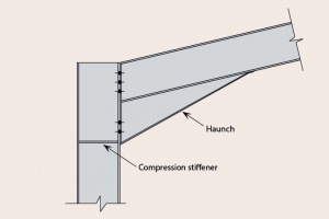
Portal frames are low-rise structures, comprising columns and rafters, connected by moment-resisting connections. The resistance to lateral and vertical actions is provided by the rigidity of the connections and the bending stiffness of the members, which is increased by a substantial haunch to reinforce the rafter sections. This form of continuous frame is stable in its plane and provides a clear span that is unobstructed by bracing. Bracing is provided in the longitudinal direction, between frames.
Portal frames are structurally efficient and lightweight, accounting for over 90% of the single-storey market in the UK. Portal frames are used for industrial, storage , retail and commercial applications.


In addition to a primary steel structure, portal framed buildings also commonly include:
- Secondary, thin gauge cold-rolled steel members (purlins and side rails) which restrain the primary steel members and support the cladding
- Profiled steel wall and roof cladding.
[top]Member design to BS EN 1993
Steel member design is based on the requirements given in BS EN 1993-1-1[7] . The overall process in member design involves:
- Classification of the cross section
- Cross-sectional resistance
- Member buckling resistance
- Resistance to combined axial loading and bending, where applicable.
Connections
The cost of connections is a significant proportion of the overall cost of the structure and the use of standardised, simple details is recommended wherever possible. Moment resisting connections will undoubtedly be more expensive than the nominally pinned connections used in braced construction .
Design of joints in steel structures in the UK is covered by BS EN 1993-1-8[10] and its UK National Annex[14]
BS EN 1993-1-1[7] requires that connection behaviour be accounted for in frame analysis, if it is significant. Nominally pinned connections and continuous connections may be modelled as pinned and rigid (respectively) in the analysis, but semi-continuous joint behaviour should be taken into account.
BS EN 1993-1-8[10] provides numerical methods to classify a joint, but offers the option that joints may be classified on the basis of previous satisfactory performance. The UK National Annex[14] specifies that joints designed in accordance with the industry standard guides (on nominally pinned and moment-resisting connections) are nominally pinned and rigid respectively. Classification in accordance the guidance in the UK NA is recommended.
Simple connections
Simple connections are nominally pinned connections that transmit end shear only and do not transfer significant moments. This assumption underpins the design of multi-storey braced frames in the UK, in which the beams are designed as simply-supported and the columns are designed for axial load and the small nominal bending moments induced by the end reactions from the beams.
- Nominally pinned connections


Simple connections include:
- Beam-to-beam and beam-to-column connections using:Partial depth end plates
- Full depth end plates
- Fin plates
- Column splices (bolted cover plates and end plates)
- Column bases
Moment-resisting connections
Moment resisting connections are used in continuous frames . Connections in multi-storey frames are most likely to be full depth end plate connections and extended end plate connections.
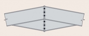
Connections in portal frames will be haunched at the eaves, often with stiffeners in the column member. The apex connection may have a small haunch or a simple extended end plate.
Moment-resisting connections may also be provided by providing a welded connection between members.
- Typical portal frame connections
FAILURE CRITERIA :
Structural engineers design buildings and other structures to resist a wide variety of forces. The different types of forces include the mass of the contents of the structure including the structure itself; transient forces from the occupancy of the structure (i.e. people moving inside the structure, equipment operating inside the structure, etc…); and environmental forces such as wind, earthquake, snow and rain. Certain structures may be required to withstand impact forces such as from blasts or missiles.
Steel has evolved over the last 100+ years to be a widely used material in structures. The availability, economy, high strength to weight ratio, ductility and elasticity are just a few factors that make steel such a popular building material. However, steel does have several disadvantages that must be taken into consideration when designing a structure.
A few limitations of steel include susceptibility to corrosion, reduction in strength when exposed to temperatures normally encountered in most fires, susceptibility to fatigue when loaded cyclically and susceptibility to buckling when under high compression and flexural stresses. In addition to these limitations, a design engineer must ensure their steel structure is robust enough to prevent the following types of failure:
• Shear failure
• Flexural failure
• Compression failure
• Tensile failureShear Failure
Shear failures will typically occur in connections between members (i.e. member to column connection, member to girder connection, etc…). Designing a connection is not an easy task. Connections typically have high shearing forces that an engineer must consider when designing the connection. A failure can occur if the structural engineer underestimates the design force the connection is to withstand. Common connections in steel structures may be made with bolts or welds or a combination of both.
Flexural Failures
Flexural failures occur in flexural members such as members and girders, and, in some cases, compression members such as columns that are subjected to bending stresses. Flexural members typically fail when flexural loadings cause the element to buckle. Because steel is strong, steel members are designed to be slim and efficient which may put them at risk of buckling. Heavier, stocky members are less susceptible to buckling.
Flexural loadings create tension and compression forces in members. Lateral torsional buckling occurs when the high compression forces causes an unrestrained section of the member to buckle and laterally displace. Providing lateral restraint to a member helps ensure it will not buckle. However, a member may still fail should the stresses resulting from a flexural loading condition exceed the material strength of the member.
Compression Failures
Compression failures typically occur in compression members, such as columns and braces, when the compressive axial force applied to the element caused the element to either buckle or become overstressed.
Similar to beams, column and brace members subjected to high compressive stresses may experience buckling. A consideration to take into account when designing a column is its slenderness ratio (ratio of cross sectional geometry to length of member); a member with a high slenderness ratio is more susceptible to buckling than one with a lower ratio. Members with low slenderness ratios may still fail when the compressive stresses exceed the material strength of the member.
Tensile Failures
Tensile failures generally occur in brace members or hangers. This type of failure occurs when the steel member is stretched to a level that exceeds the material strength of the member. This occurs in stages, the first being yielding, necking and then the material fails at the point with the least cross section area.
Steel is a very strong material and very reliable in structural construction of buildings. Its effectiveness, however, is only guaranteed when the steel is properly designed to withstand the imposed forces. Poor design can lead to the above-mentioned failures of steel structures.
CODAL SPECIFICATIONS:
https://thelibraryofcivilengineer.files.wordpress.com/2015/09/irc-24-2001-standard-specifications-code-of-practice-for-road-bridges-steel-road-bridges.pdf
How to Determine Loads while Designing a Steel Structure ?
Determination of the loads for which a structure has to be proportioned is an important task in a design. The various loads that are likely to act on a structure and the possible combinations of such loads that can act are all points to be considered.
Dead load refers to the weight of a structure. It is necessary to estimate reasonably the dead load before a structural analysis is made. After a preliminary design, the actual weight should be determined and compared with the originally estimated values and the necessary corrections should be made.
Loads other than dead loads may be considered as live loads. The live loads may be either steady or unsteady i.e., they may be fixed or movable or moving. They may be applied slowly or suddenly.
The usually considered live loads are the following:
(i) The weights of people, goods, furniture and any machinery in a building.
(ii) The weight due to traffic on a bridge.
(iii) The weight due to accumulation of snow.
ADVERTISEMENTS:
(iv) Dynamic forces caused by moving loads.
(v) Forces due to wind action.
(vi) Pressure forces exerted by liquids in storage tanks.
(vii) Temperature variations creating forces when expansions and contractions are prevented.
ADVERTISEMENTS:
Besides these, earthquakes can induce dynamic forces.
Gravity loads determined from weights of structures are static loads. Loads in motion produce greater forces than when they are static. A dynamic force produced by sudden change in velocity is an impact load which can be lateral or longitudinal. Motion on a curved path can also cause a lateral force. Longitudinal forces are caused due to acceleration or deceleration of vehicles.
The IS 875 Code on loading standards gives details of loads to be considered on structures.
Brief details of the same are given below:
ADVERTISEMENTS:
A structure is subjected to various types of loads like dead loads, live loads, wind loads etc.
Dead Load:
This consists of the weight of walls, partitions, floors, roofs including the weights of all other permanent constructions in the building. A schedule of unit weights of building materials is given in I.S.: 1911 code.
The I.S. recommendations for dead load are given below:
Provision for Loads from Partition Walls:
ADVERTISEMENTS:
Loads due to partitions shall be assessed on the basis of the actual constructional details of the proposed partitions and their positioning in accordance with plans, and the loads thus assessed shall be included in the dead load for the design of floors and the supporting structures.
Where, however, the actual loads of the partitions cannot be assessed beforehand owing to lack of knowledge of the final positioning of the partitions, the floors and the supporting structures shall be designed to carry, in addition to other loads, a uniformly distributed load per square metre of not less than 33⅓ per cent of the weight per metre run of finished partitions over the entire floor area subject to a minimum uniformly distributed load of 1000 N/m2 in the case of floors used for office purposes.
No partition shall be allowed to be erected which may, in effect, result in stresses greater than those allowed for in the design.

Live Loads on Floors:
Live Loads on Floors of Various Types of Buildings:
Live loads on floors shall comprise all loads other than dead loads. The minimum live loads on different floors for different uses shall be as given in the Table. The loads specified in this table are uniformly distributed static loads N/m2 on the plan area and provide for normal effects of impact and acceleration, but do not take into consideration special concentrated loads, snow loads and other loads.
Reduction in Floor Live Loads:
The following reductions in assumed total live loads on floors may be made in designing columns, walls, peirs, their supports and foundations:

No reduction shall be made in the case of warehouses, garages and other buildings used for storage purposes and for factories and workshops designed for 5000 N/m2. However, for buildings, such as factories and workshops, designed for a live load of more than 5000 N/m2 the reductions given in the table may be made provided that the loading assumed for any column, etc. is not less than it would have been if all the floors had been designed for 5000 N/m2 with no reduction.
Where, a single span of a beam or girder supports not less than 50 metre2 of floor at one general level, the live load may be reduced in the design of the beam or girder by 5 per cent, for each 50 metre2 supported, subject to a maximum reduction of 25 per cent.
This reduction or that given in the table, whichever is greater, may be taken into account in the design of columns, supporting such a beam, but, shall not be made where the floors are used for storage purposes nor in the weight of any plant or machinery which is specifically allowed for.
Live Loads on Roofs:
Live Loads on Various Types of Roofs:
On flat roofs, sloping roofs and curved roofs allowance for live load shall be are given below:
Roofs of buildings used for promenade or incidental assembly purposes shall be designed for a minimum load of 4000 N/m2 or heavier, if required.
Snow Load:
If a roof is subjected to snow load, it should be designed for the actual load due to snow or for the live loads specified in table on Table 3.2 whichever is more severe. Actual load due to snow will depend upon the shape of the roof and its capacity to retain the snow and each case shall be treated on its own merits.
In the absence of any specific information, the loading due to the collection of snow may be assumed to be 25 N/m2 per 10 mm depth of snow. The possibility of total or partial snow load should be considered, that is one-half of the roof fully loaded with the design snow load and the other half loaded with half the design snow load. In the case of roofs with slopes greater than 50°, snow load may be disregarded; where, however, there are possibilities of formation of snow pockets, these should be taken into account.


Load Due to Rain:
On surfaces whose positioning, shape and drainage system are such as to make accumulation of rain water possible, load due to such accumulation of water and the live loads for the roofs as given in the table shall be considered separately and the more critical of the two shall be adopted in the design.
Horizontal Loads on Parapets and Balustrades:
Where it is desired to design parapets and balustrades against horizontal pressures, loads shown in table below expressed as horizontal loads acting at handrail or coping level shall be provided for. The values given are for guidance only and where values for actual loadings are available, they shall be used instead.

Impact and Vibrations:
For structures carrying live load which induce impact or vibration, as far as possible, calculations shall be made for the increase in the live load due to impact or vibration.
In the absence of sufficient data for such calculation, the increase in the live load shall be as follows:
Concentrated Live Loads with Impact and Vibrations:
Concentrated live loads with impact and vibration which may be due to installed machinery shall be considered and provided for in the design. The impact factor shall not be less than 20 per cent which is the amount allowable for light machinery.
Concentrated Imposed Loads with Impact and Vibration:
Concentrated imposed loads with impact and vibration which may be due to installed machinery shall be considered and provided for in the design. The impact factor shall not be less than 20 per cent which is the amount allowable for light machinery.
Provision shall also be made for carrying any concentrated equipment loads while the equipment is being installed or moved for servicing and repairing.
Impact Allowance for Crane Girders:
For crane gantry girders and supporting columns, the following allowances shall be deemed to cover all forces set up by vibration, shock from slipping or slings, kinetic action of acceleration, and retardation and impact of wheel loads:

Forces specified in (c) and (d) shall be considered as acting at the rail level and being appropriately transmitted to the supporting system. Gantry girders and their vertical supports shall be designed on the assumption that either of the horizontal forces in (c) and (d) may act at the same time as the vertical load.
Overloading Factors in Crane Supporting Structures:
For all cranes and charging cranes, where there is possibility of overloading from production considerations an overloading factor of 10 per cent of the maximum wheel loading shall be taken.
Crane Load Combinations:
In the absence of any specific indications, the load combinations shall be indicated below:
Vertical Load:
In an aisle, where more than one crane is in operation or has provision for more than one crane in future, the following load combinations shall be taken for vertical loading:
(a) Two adjacent cranes working in tandem with full load and with overloading to the previous clause.
(b) For long span gantries, where more than one crane can come in the span, the girder shall be designed for the crane fully loaded with overloading plus as many loaded cranes as can be accommodated on the span but without taking into account overloading according to the previous clause to give the maximum effect.
Lateral Surge:
For design of columns and foundations, supporting crane girders, the following crane combinations shall be considered:
(a) For Single-Bay Frames:
Effect of one crane in the bay giving the worst effect shall be considered for calculation of surge, and
(b) For Multi-Bay Frames:
Effect of two cranes working one each in any of two bays in the cross-section to give the worst effect shall be considered for calculation of surge force.
Tractive Force:
When one crane is in operation with no provision for future crane, tractive force from only one crane shall be taken.
Where more than one crane is in operation or there is provision for future crane, tractive force from two cranes giving maximum effect shall be considered.
Note:
Lateral surge force and longitudinal tractive force acting across and along the crane rail respectively, shall not be assumed to act simultaneously. However, if there is only one crane in the bay, the lateral and longitudinal forces may act together simultaneously with vertical loads.

Note:
In the case of guard parapets on a floor of multi-storeyed car park or crash barriers provided in certain buildings for fire escape, the value of imposed horizontal load (together with impact load) may be determined.
Impact Allowance for Lifts, Hoists and Machinery:
The imposed loads specified above shall be assumed to include adequate allowance for ordinary impact conditions. However for structures, carrying loads which induce impact or vibration, as far as possible, calculations shall be made for increase in the imposed load, due to impact or vibration.
In the absence of sufficient data for such calculation, the increase in the imposed loads shall be as follows:
Live Loads on Roofs:
The I.S. code has stipulated the allowance for live load on flat roofs, sloping roofs and curved roofs (Table 3.4).

Note:
For special types of roofs with highly permeable and absorbent material, the contingency of roof material increasing in weight due to absorption of moisture shall be provided for.
The loads given above do not include loads due to snow, rain, dust collection etc. The roof shall be designed for imposed loads given above or snow/rain loads whichever is greater.


Provision shall also be made for carrying any concentrated equipment loads while the equipment is being installed or moved for servicing and repairing.
For crane gantry girders and supporting columns, the allowances in the above table shall be deemed to cover all forces set up by vibration, shock from slipping of slings, kinetic action of acceleration and retardation, and impact of wheel loads.
The horizontal forces specified in (c) and (d) shall be considered as acting at the rail level and being appropriately transmitted to the supporting system for both electric and hand-operated cranes.
Gantry girders and their vertical supports shall be designed on the assumption that either of the horizontal loads (c) and (d) may act at the same time as the vertical load.
Wind Load on Buildings:
The I.S. 875 specification has stated that for structures of various plan shapes other than rectangular plan shape, the external pressure acting on the projected area in the plane perpendicular to the wind shall be the product of basic pressure stipulated by the code and the shape factors given in the table 3.5.

Note 1:
In the case of projections above the general roof level, the base width shall be taken as the width of the construction where it rises from the surface of the roof; and the height governing the ratio of height to base width shall be that from the roof surface to the top of the construction.
Note 2:
The division of wind load into that acting on windward and leeward sides shall be the same as that for rectangular buildings as affected by the openings.
- click here for :Steel structure design calculation steel structure design example


Thanks for sharing this informative post. When I read your post I understood the correct use of different types of fasteners. If anyone is looking for high-quality Inconel 718 Fasteners, you can visit this official site Vision Alloys.
ReplyDeleteAuthentic platform to find the leading nut bolt industry here. Deal with Sumit Impex for Quality Din 1.4401 Fasteners at true cost.
ReplyDeleteI'm really impressed with the details you give. This is an interesting article for me as well as others. Thanks for sharing such articles here. Duplex S32205 Seamless Pipe.
ReplyDeleteThis post was very helpful for me. I've been trying to improve this and your tips were spot-on.
ReplyDelete904L Stainless Steel ERW Pipe
This post was exactly what I was looking for, You answered all of my questions.
ReplyDeleteCopper Single Disconnecting Earth Bar
Your post was so well-organized and easy to follow. Thank you for breaking down in a way that's easy to understand.
ReplyDeleteHastelloy C276 Bolt
I found your article to be very thought-provoking It's clear that you have a deep understanding of the industrial sector and its challenges.
ReplyDeleteAISI 316 SS Shim
Thank you for providing a balanced perspective. It's important to consider both the opportunities and challenges facing the industrial sector.
ReplyDeleteUNS S32205 sheets
I had to stop and think about a few things after reading what you had said. You obviously know a lot about the difficulties that manufacturers face. If you're looking for Square Pipe visit M.S Square Pipe suppliers .
ReplyDeleteYour post was very informative and easy to understand. I would have been lost without that clarification. The instructions on this page helped me tremendously.Check out Welten 780E plate if you're interested to find out more about plates.
ReplyDeleteI value the extensiveness of your explanation. I know I'm not alone in thinking this is an interesting read. Check out my site if you want to know more about 316L stainless steel round bar.
ReplyDeleteThank you for clarifying everything so well. I had some second thoughts after reading your work. You obviously have a lot of business savvy. For further details on the Duplex S31803 Plate, check out my website.
ReplyDeleteWe enjoyed your article. You've clearly researched industry. WN Flanges ? Visit us.
ReplyDelete